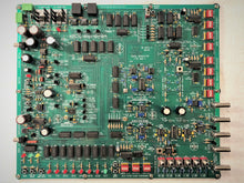
The Type MOD-1 Signal Modulator board is intended as a training platform in the design and implementation of classical textbook modulation. The MOD-1 interfaces with the Type NCD-1 Non-coherent, the Type CD-1 Integrate & Dump Coherent and the Type COS-1 Costas/squaring loop demodulators. Together with the Type NS-1 Noise Source and the Type BER-1 Bit Error Ratio (BER) Measurement board, a complete system can be integrated for the study of modulation, demodulation, signals and noise. The Type MOD-1 Signal Modulator generates and provides:
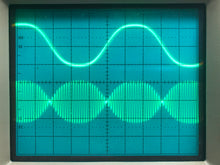
- ASK, FSK, BPSK, DPSK, QPSK, Offset-QPSK (OQPSK) and 8QAM
- Independently adjustable I and Q-Level carriers
- Independently selectable FSK(MARK) and FSK(SPACE) frequencies
- Independently adjustable BPSK phase (0 ~ 180 degrees (antipodal))
- Selectable Data Rates of 4, 8, 16, 32 and 64kbps
- 20-stage linear-feedback maximal-length pseudorandom data
- 64kbps 8-bit PCM audio CODEC
- Selectable 8, 16, 32, and 64kbps CVSD audio CODEC
- Selectable external audio, internal on-board microphone or 16-second stored audio sound recording (Chipcorder) of your choice (play once or repeat mode)
- On-board independent, selectable, I/Q-Data 8th-order linear-phase baseband data filters with bandwidths from 0.8Rb ~ 1.2Rb in 1% steps (Rb = Data Rate)
- On-board selectable output modulation signal attenuator toggle switches from 0 ~ 31-dB in 1-dB steps
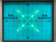
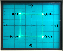
- I/Q data outputs for signal constellation study
- Unmodulated in-phase and quadrature carrier outputs
- Test Mode (Test Bit Mode Select) for I-Data, Q-Data and Amplitude-Data bits to observe carrier phase, amplitude and constellation data point(s)
- Pseudorandom data output Test Mode (Test Data Select) that tests all modulation types
- Connects to Types NCD-1, CD-1 and COS-1 demodulators via CAT-6 cable to transmit/receive TX Data/Recovered Rx Data and TX Clock/Regenerated RX Clock for BER measurements
- Loops back recovered 8-bit PCM and CVSD audio for quality comparison under bit errors during BER testing
- On-board audio power amplifier to drive external speaker (not supplied)
- DC power inputs are polarity protected
The Type MOD-1 Signal Modulator board comes with:
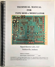
- Technical Manual that covers Configuration, Operation, General Theory, Block Diagrams, Schematic Diagrams with complete design philosophy. 195 Pages, 184 Figures, 29 Tables. Parts List. A complete course by itself.
- Five, 3-foot length RG-58/BNC 50-ohm cables
- One, 3-foot length CAT-6 (or CAT-5e) network cable
- 33, 2-pin configuration jumpers
- Two, 12-VDC wall-mount power supplies (or you can use your own)
- One, alignment tool.
- Type MOD-1 board outline is (width x depth) 14" x 12" (355.6 x 304.8mm).


